Scraper

Scraper conveyor, medium single chain scraper, 22 single chain slide
- Introduce: I. Overview of said SGD420 / 22 type scraper conveyor is …
Product details
I. Overview of said
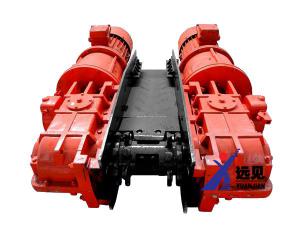
SGD420 / 22 type scraper conveyor is mainly used for conveying coal in the blasting mining face of narrow and thin coal seam, the inclination angle is not more than 25 °. The baffle coal plates on both sides of the middle trough can be used to transport coal along the trough. The SGD420 / 22 type scraper conveyor is a single-chain side type. Its type, size and main technical performance parameters comply with the provisions of MT / T105-93 "Mine Scraper Conveyor Types and Parameters", and the product has a high level of standardization and user level.
2. Main technical features
The main technical parameters
parameter name | unit | Parametric value | parameter name | unit | Parametric value | |||
Conveyor model | SGD420 / 22 | electric motor | model | YBS-22-4 | ||||
Throughput | t / h | 60 | power | K / w | twenty two | |||
Design length | m | 100 | Rotating speed | r / min | 1470 | |||
Head height | mm | 540 | Voltage | V | 380/660 | |||
Scraper chain speed | m / s | 0.66 | Scraper chain | Circular chain specifications | mm | Φ18 × 64 | ||
Middle slot | Length × width × height | mm | 1200 × 420 × 150 | Tensile strength of each circular chain | KN | ≥250 | ||
Quality per section | kg | 66 | Single chain center distance | mm | 700 | |||
Machine quality | kg | 10600 | Reducer transmission ratio | 22.24 | ||||
3. Main part structure and performance description
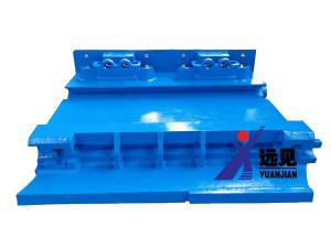
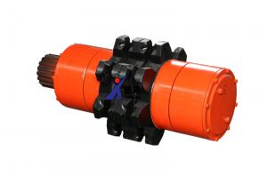
(1) Transmission Department
The transmission part (Figure 2) is mainly composed of electric motor, shaft reducer, reducer, transmission sprocket, chain tensioner, blind shaft, head frame, etc. The motor, reducer and head frame are arranged in parallel. The motors are connected together through the connection cover, and then they are hung on the head frame in parallel by the M24 bolts. The input shaft of the reducer is connected to the electric shaft through the wooden coupling. The support of the output shaft extending into the side plate of the head frame is connected with one end of the head sprocket with a spline. The other end of the head sprocket and the blind shaft extension installed on the other side of the head frame are also splined. connection. The torque generated by the motor is transmitted to the reducer through the wooden coupling, and then reduced through the reducer to transmit the torque to the machine head sprocket through the safety pin, thereby driving the scraper chain to run in the middle groove to achieve the purpose of transporting coal. In case of abnormal phenomena such as overload or scraper chain scraping in use, the safety pin will be cut first, so that the torque of the motor cannot be transmitted to the sprocket of the machine head, and the motor runs at no load, which plays a role in protecting the motor and other components. In order to facilitate the overall movement of the conveyor, a fixed beam and a support beam are installed at the lower part of the head frame. In order to adapt to the small space of thin coal, the transmission part is installed on the fixed beam with a total height of only 540mm.
1. Motor
The matching motor of SGD420 / 22 type scraper conveyor is YBS-22-4 explosion-proof motor. In order to start at full load, the starting torque and maximum torque of the motor are 2.7 times the rated torque. The motor's desire for temperature rise is large, and it can run well under the condition of frequent starting.
2. Reducer
SGD420 / 22 type scraper conveyor adopts JS-30 type reducer, which is three-stage deceleration and involute gear transmission. The total transmission is 22.24. The *** level is a circular arc bevel gear, the second level is a cylindrical helical gear, and the third level is a cylindrical spur gear. The technical parameters of gears at all levels are shown in Table 1.
Total series | Number of teeth | Modulus | Helix angle | Transmission ratio | |
Gear ratio | Total transmission ratio | ||||
***level | 14.33 | ms = 6 | 35 ° | 2.357 | 22.24 |
second level | 15.52 | mu = 5 | 10 ° | 3.466 | |
Third level | 18.49 | m = 6 | 2.722 | ||
This reducer has a larger improvement in structure than the general mining cone and cylindrical gear reducer. The common shaft (as shown in Figure 3) adopts a set of double-row radial spherical roller bearings and two sets of single-row radial balls Bearing. The axial force generated when the arc bevel gear rotates is borne by two sets of single-row centripetal bearings. Double row radial ball roller bearings rely on splash lubrication. Two sets of single row radial thrust ball bearings are lubricated with No. 2 sodium base grease. The axial placement and axial clearance of the circular arc bevel gear are ensured by adjusting the adjustment pads at both ends of the single-row radial thrust bearing.
The axial clearance of the second shaft is ensured by adjusting the adjustment pads on both sides of the fixed end bearing. The other bearing is in a free state in the axial direction. The use proves that the structure improves the lubrication condition of the two bearings compared with the old structure, improves the contact accuracy of the arc bevel gear, and extends the service life of the bevel gear.
Axial clearance of each shaft of reducer:
*** Axis: 0.06 ~ 0.08mm
Second axis: 0.08 ~ 0.15mm
The third axis: 0.20 ~ 0.30mm
Fourth axis: 0.20 ~ 0.35mm
The box of the reducer is symmetrical up and down to meet the different needs of the left and right work underground. When changing the left and right working surfaces, install an air plug on the upper cover and an oil plug on the lower cover.
The reducer uses No. 150 extreme pressure gear oil or No. 22 hyperbolic gear oil to lubricate the gear, and the injection amount is the tooth width of the submerged large bevel gear.
3. Headstock (Figure 5)
The headstock is an integral welded component. The axis hole of the transmission sprocket is the positioning hole for installing the reducer or the blind shaft. There are holes for inserting chain hooks on the upper edges of the two sides of the head frame. Each side plate has a φ200 and 6 φ26 holes to install the reducer. The Φ26 hole is the hole for installing the coupling bolt between the reducer and the head frame.
The head frame is equipped with a detachable fixing frame and a chain puller (connected to the fixing frame with pins). The chain puller can force the scraper chain in motion to disengage the sprocket at the point where the sprocket runs away, to avoid accidents caused by "rolling chain".
4. Tight chain device
The chain tightening device is used for tensioning the chain of scraper when installing, disassembling or changing the length of laying and adjusting the tension. The tight chain device includes two parts of the tight chain hook. The chain tensioner uses a friction belt type chain tensioner, which is installed on the second shaft of the reducer. The tight chain hook is composed of Φ18 × 64 circular chain and hook.
When tightening the chain, insert one end of the two tightening chain hooks into the Φ38mm holes on both sides of the head frame, and the other end into the vertical ring of the scraper chain. Head chain transmission line. Then jog the reverse car, tension the scraper chain, and turn the chain tensioner eccentric wheel through the handle of the chain tensioner to keep the scraper chain tensioned, and then remove the extra chain link or replace the appropriate adjustment chain. Connect the two ends of the scraper chain to make the entire scraper chain form a ring-shaped closed chain to achieve the purpose of tightening the chain. The tension of the scraper chain should be lowered under the sprocket of the machine head when running at full load. After the chain is connected, the tightening chain hook is removed and the eccentric wheel of the tightening device is turned in the opposite direction to disengage the brake belt from the braking wheel to complete the tightening chain operation.
(2) The middle part
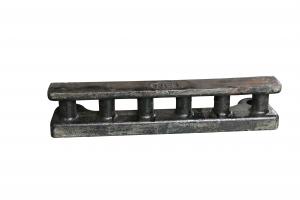
1. The middle slot (Figure 7)
One of the main components of the central trough system is the coal transportation channel. There are two kinds of cold groove groove steel or rolled groove groove steel in the middle groove groove steel. The middle groove composed of cold-pressed groove top steel is welded by 8mm-thick cold-pressed groove top and 6mm-thick middle plate. The middle groove composed of rolled groove top steel is welded by 8mm thick rolled groove top and 6mm thick middle plate, and the length is 1200mm. A connecting pin is welded to one end of the groove upper, and the connecting pin is inserted into the groove of the adjacent middle groove upper to realize mutual positioning. The middle groove can be offset by 3 ° in the horizontal plane to meet the needs of the uneven floor floor and the overall movement of the machine. A carbon arc surfacing 1.5 ~ 2mm thick wear-resistant alloy is used for the position of the middle plate chain path to increase the wear resistance and improve the service life. According to the need, the support of the coal baffle plate can be welded on the middle slot of each section, and the coal baffle plate is installed to improve the transportation volume.
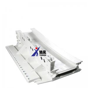
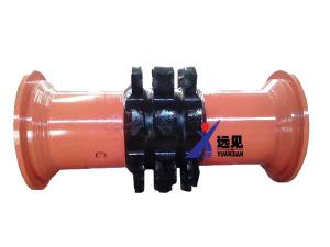
2. Transition slot (Figure 8)
In order to adapt the scraper chain to run smoothly from the middle groove to the machine head sprocket, a transition groove is provided between the middle groove and the head frame. The transition groove is a chute with different heights at both ends, which is connected to the middle groove and the head frame The inner edge of the upper groove of the end is welded with a 1.5 to 2mm thick wear-resistant alloy block by carbon arc. After the wear block is worn, it can be purchased and replaced from the manufacturer.
3. Adjustment slot
The structure of the adjusting groove is the same as that of the avoiding groove, but the length is shorter. The adjustment slot length is 600mm. When the length of the working surface changes or the conveyor slides down to adjust the installation length of the conveyor, it is only necessary to adjust the groove.
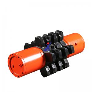
(3) Scraper chain (Figure 9)
The scraper chain is a traction component for conveying coal by a conveyor, and is composed of a circular chain, a scraper, and an open-type connecting endless belt. Each ring chain has a length of 850mm and is composed of 17 single rings. The scraper adopts the transmission structure of double side chain. The scraper adopts rolling scraper.
The connecting ring adopts the traditional open structure. The connecting ring is matched with M16 bolts with strength of 8.8 and nuts with grade 8. In order to ensure the strength of the connecting ring, the connecting ring and the supporting bolts and nuts must be used and replaced according to the strength level. The strength grade of the ring chain is grade B GB / T12718-2001. The strength grade of the open connection ring is grade B MT71-1997. The scraper spacing of the product is 700mm. The scraper chain is installed with the connection.
To adjust the tension of the chain, there are seven kinds of adjustment chains.
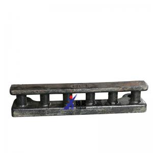
(4) Tail of the machine (Figure 10)
The tail is composed of a tailstock and a tail shaft. The tailstock has a total length of 1400mm and a height of 346mm. The upper end of the connection between the tailstock and the middle groove is welded with a wear-resistant alloy block on the upper edge of the steel, thereby improving the service life of the tailstock. The column feet on both sides of the tailstock are used to support and fix the tail blades of the machine. The tail shaft is installed on the tail frame, and is composed of a guide sprocket, sleeve shaft, positioning sleeve, bearing seat, cushion seal and two sets of 3613 bearings. The guide wheel of the tail shaft of the machine adopts a sprocket or drum structure, both of which can ensure the gong ring is properly meshed on it, reducing operating accidents.
4. Installation and trial operation
(1) The test run should be installed on the surface before the machine goes down the well.
(2) The installation sequence of the working face and the disassembly of the assembly components should be worked out before the machine goes down the well.
(3) Before installation in the underground working face, the components shall be numbered and transported to the underground installation site in sequence according to the installation order and installation position. Random accessories and tools used for installation and various connecting parts should be brought to the underground installation site according to specifications and varieties.
(4) Installation order of transmission part
1. The headstock and the fixed beam are well connected at the installation site.
2. The reducer, coupling cover and motor can be connected into one body first, and then connected with the head frame. The coupling and motor can also be installed after the reducer is connected to the head frame. The reducer should be installed on the side near the empty area. The seal housing positioning part of the output (fourth) shaft of the reducer should coincide with the support hole of the head frame.
When installing the reducer, pay attention to protect the input (***) shaft of the reducer.
3. Install a blind shaft in the bearing hole of the sprocket on the other side of the head frame. The position of the blind shaft bearing seat should coincide with the support hole of the head frame.
4. Install sprockets on the shaft extensions of the fourth shaft and the blind shaft of the reducer, and then install the half roller.
5. Install chain puller and tongue plate, chain puller and sprocket, tongue plate and roller are not allowed to have friction.
6. Install friction belt type chain tensioner on the shaft extension of the second shaft of deceleration.
(5) Install the transition groove, and install the scraper chain in the lower groove body. Pay attention to the installation direction of the scraper, with the nut facing backward. Do not twist the ring chain. The welded side of the upright ring of the circular chain must not be in contact with the middle groove mid plate. The lower chain end of the lower chute head should be connected with two to several suitable adjustment chains so that it can be removed smoothly when the chain is tightened. The growing chain. When connecting, pay attention to the bolts on the link ring must be tightened.
(6) Install the lower scraper chain and the middle groove in sequence. The lower scraper chain can also be connected to the long groove and pulled in by the steel rope pre-worn in the lower groove body.
(7) After installing the transmission part and the tail part, install the upper scraper chain in the middle groove over the entire length of the laying.
(8) The head and tail of the machine must be fixed with columns to prevent instability when the conveyor is turning and the conveyor is lifted up longitudinally under tension.
(9) Turn on the power. Test the running direction of the motor.
(10) Inject 150 No. extreme pressure gear oil or No. 22 hyperbolic gear oil into the reducer box, and the oil injection amount is the tooth width of the large arc bevel gear. *** Inject 2 # sodium base grease into the shaft seal oil chamber 2/3.
(11) Tension the scraper chain. First put the scraper chain protruding under the nose frame on the nose sprocket, the upper groove and the end of the scraper chain are fixed on the nose frame with a tight chain hook, and the motor is jogged in reverse, after the chain is tightened Then, through the handle of the chain tensioner, turn the eccentric wheel to brake the reducer to keep the scraper chain tensioned. Select the appropriate length of the adjustment link and the chain, remove the tight chain hook, then jog the motor forward and turn the chain tensioner eccentric at the same time to loosen the brake belt and brake wheel to complete the chain tightening operation.
(12) Start the conveyor to make the scraper chain run empty for two to three weeks, carefully check whether the scraper chain is installed correctly, whether the scraper is stuck or not, and whether the transmission part is normal.
(13) After checking and adjusting the normality of each department, it should be driven continuously for 15 to 30 minutes in empty operation. Further check the problems in the installation process, and adjust to eliminate to achieve normal.
(14) After the hole operation test is normal, a full-load operation test shall be carried out, and the length of the divided coal shall be determined according to the test data.
(15) After everything is normal, the machine can be put into use or production use.
V. Use and maintenance
(1) Operation
1. Before the start of each shift, patrol the full length of the working surface, check all parts and their joints for abnormal phenomena, and confirm that there is no problem before driving.
2. Before the machine is started, you should first jog the test car to check whether there are scratches and stuffy cars in each moving part. It can be officially started after it is normal.
3. According to the full-load operation test and the actual situation of the working face, determine the length of coal falling in the staged blasting. Before coal breaks, the conveyor should run for a period of time. Generally stop when blasting.
4. When the machine is running, the driver and follow-up maintenance personnel should stick to their work positions. Observe the operation of the machine, and check the temperature and sound of the bearings of the motor and reducer at any time for abnormal phenomena. If abnormal conditions are found, they should be stopped immediately for further detailed inspection and troubleshooting.
5. During the operation, pay attention to the meshing state of the scraper chain and the sprocket at any time. If the scraper chain is found to be too loose or too tight, the scraper chain must be disassembled and the chain tightened again.
6. When the machine head overlaps the down-slot transfer machine, the appropriate unloading height should be maintained. To avoid the unloading height is too small to bring the scraper chain back to coal or the unloading height is too large to throw coal to the bottom plate.
7. Check the tightening state of the scraper chain bolts once a day, and loosen the screws. After the spring washer fails, it should be replaced in time. During maintenance, the strength level of the newly replaced scraper bolts and nuts must meet the requirements of the instructions.
8. During the operation, the scraper encounters abnormal conditions such as scratching the card, and when the insurance pin is cut off, you should first check the cause and eliminate the fault, and then replace the new insurance pin.
9. Frequently check the temperature rise, sealing and running conditions of the motor reducer, blind shaft and tail shaft. If any abnormality is found, it should be checked or replaced in time.
10. Regularly check the lubrication of each running part. Fill the reducer input shaft, output shaft, blind shaft, tail shaft bearing regularly with the specified grease.
11. When the speed reducer is overhauled and reassembled, the axial clearance of each shaft should be readjusted with an adjustment washer. The shaft clearance parts of each shaft are described in this manual.
(2) Routine maintenance and precautions
1. In operation, always pay attention to whether each transmission component is safe and reliable. The tension of the scraper chain and whether there is any looseness or misalignment at each connection port. Whether the scraper chain is scratched.
2. The roller bolts of the transmission sprocket should be checked once a day to ensure the tightening state, and loose ones must be tightened. If bolts and other tightening damages are found, they should be replaced immediately.
3. During the operation of the scraper chain, the tightening state of the bolts should be checked once a day, and loose ones must be tightened. After the spring washer fails, it should be replaced in time. During maintenance, the strength level of the newly replaced scraper bolts and nuts meets the requirements of the instructions.
4. There should be a certain number of spare parts for safety pins, scrapers, adjustment chains, etc. in the underground, and they should be kept in a safe place so that they can be used as needed.
5. The bending angle of the adjacent middle groove should be kept within the allowable range of 3 °. In case of faults or large fluctuations in the bottom plate, the bottom plate should be properly treated to prevent the chute from being bent too much and causing the scraper to block and move the chute , There must not be a part of excessively protruding ahead, so as to avoid the chute out of joint.
6. All sealing parts and shaft openings should be checked frequently for the sealing condition of the device. If the leakage is found, it needs to be replaced in the maintenance class when it is serious. Generally, it is replaced within the plan.
7. Always pay attention to clean up the floating coal at the machine head to prevent the coal from returning to the chain and increase the running resistance.
8. The conveyor adopts the overall manual movement. Because the middle groove is lighter, it can generally be moved with a crowbar. The machine head is heavier and can be moved to a new working position with a small winch or other pushing equipment in the working surface. After the shift is completed, the head and tail of the machine must be laid with fixed pillars.
6. Optional accessories (coal baffle)
When the machine is used for transportation along the trough or working surface and the transportation volume needs to be increased, coal baffles can be installed on the machine head, transition trough and middle trough. Transportation volume. The middle groove of the coal baffle and the adjustment groove are installed in pairs, with 1.2mm and 0.6mm specifications.
Seven, machine lubrication
Serial number | Part Name | Lubricated parts | Lubricating oil grade | Filling interval |
1 | electric motor | Bearing | Calcium sodium base grease | Oil injection during maintenance |
2 | reducer | gear | No. 150 extreme pressure gear oil or No. 22 hyperbolic gear oil | Ensure oil level and replace with new oil regularly |
3 | reducer | Input shaft K cavity | No. 2 sodium base grease | Supplement once a month |
4 | reducer | Labyrinth slot and cavity of output shaft | No. 2 sodium base grease | Supplement once a month |
5 | Blind axis | Bearing | No. 2 sodium base grease | Supplement once a month |
6 | Tail shaft | Bearing | No. 2 sodium base grease | Supplement once a month |
8. List of bearings and spare seals
Bearing list
Serial number | Code | name | specification | Quantity | Installation location |
1 | GB / T286-1994 | Bearing | 3611 | 1 | Reducer *** shaft |
2 | GB / T286-1994 | Bearing | 3612 | 2 | Reducer second axis |
3 | GB / T286-1994 | Bearing | 3613 | 3 | Reducer third axis, blind axis |
4 | GB / T286-1994 | Bearing | 3522 | 1 | Reducer fourth axis |
5 | GB / T286-1994 | Bearing | 3003126 | 1 | Reducer fourth axis |
6 | GB / T286-1994 | Bearing | 3511 | 2 | Tail |
7 | GB / T286-1994 | Bearing | 46311 | 2 | Reducer *** shaft |
Seal List
Serial number | Code | name | specification | Quantity | Installation location |
1 | GB / T34521-1992 | O-ring | 65 × 3.1 | 1 | Reducer second axis |
2 | GB / T34521-1992 | O-ring | 100 × 5.7 | 3 | Tail, reducer fourth axis |
3 | GB / T34521-1992 | O-ring | 120 × 3.1 | 1 | Reducer *** shaft |
4 | GB / T34521-1992 | O-ring | 140 × 5.7 | 1 | Reducer fourth axis |
5 | GB / T13871-1992 | Oil seal | B150 × 180 × 16 | 1 | Reducer fourth axis |
6 | GB / T13871-1992 | Oil seal | B55 × 72 × 12 | 1 | Reducer *** shaft |
7 | GB / T13871-1992 | Oil seal | B55 × 80 × 12 | 4 | Tail |
8 | GB / T13871-1992 | Oil seal | B75 × 100 × 12 | 2 | Reducer *** axis and second axis |
9 | GB / T13871-1992 | Oil seal | B85 × 110 × 12 | 1 | Blind axis |
10 | GB / T13871-1992 | Oil seal | B110 × 140 × 14 | 1 | Reducer fourth axis |
Nine, faults and treatment methods
Serial number | malfunction | Possible Causes | Prevention and treatment methods |
1 | Cut off insurance sales frequently | 1. Scraper chain severely scratches the card 2. The blasting coal falling section is too long or there is too much coal in the tank, the conveyor is overloaded 3. The back coal is severely plugged in the trough | 1. Eliminate the scraping factors of the scraper chain 2. Shorten the length of the blasting coal section 3. Clean up the bottom coal floating coal 4. Replace the insurance pin |
2 | Reducer heating sound is abnormal | 1. The gear mesh is not good 2. The gears or bearings are seriously worn, and the axial clearance of the bearings is inappropriate 3. Insufficient amount of lubricating oil, oil leakage 4. The bearing end cover is loose or the gap is uneven | 1. Adjust the meshing clearance 2. Replace worn gears or bearings, and adjust the axial clearance of bearings 3. Add oil or replace seals 4. Install the end cover, adjust the gap and tighten the bolts |
3 | Jump chain | 1. Scraper chain twist twist 2. Sprocket teeth wear seriously 3. Scraper chain is too loose | 1. Reinstall the scraper chain 2. Replace the sprocket again 3. Re-tighten the chain |
4 | Scraper cannot start normally | 1. Power failure 2. The voltage is too low 3. The magnetic starter fails 4. Excessive load, blown fuse | 1. Check whether the fuse or the connector is badly connected and may be blown 2. Check whether the voltage of the substation reaches the rated voltage and whether the line is too long 3. Check whether the magnetic starter has bad contact and repair it 4. Reduce the amount of coal loaded, eliminate the place where the chain is scraped, remove the coal back, and replace the specified fuse again |
5 | Scraper chain periodic scratch card | 1. The middle groove and the middle plate are too deformed 2. The middle slot of two adjacent sections is seriously misaligned | Replace the middle slot |
6 | Scraper chain comes out of middle slot | 1. Excessive bending of the middle groove 2. Slack chain 3. The middle groove is severely worn and deformed 4. Bending deformation of the scraper | 1. The offset of the adjacent middle slot does not exceed 3 ° when laying 2. Re-tighten the chain 3. Replace the middle slot 4. Replace or correct the scraper |
Tips: willing to spend a lot of money for products, not to buy fakes cheaply
Please look for Luoyang Yuanjian Mining Equipment Co., Ltd. ,assured products in the market.
Luoyang Yuanjian Mining Equipment Co., Ltd.