Scraper

SGD320 / 17B scraper conveyor, 17 single chain scraper, 17 double chain scraper, 17 coal slide
- Introduce: 1. Overview The scraper conveyor is mainly suitable for conveying coal in the blas…
Product details
1. Overview
The scraper conveyor is mainly suitable for conveying coal in the blasting working face of the gently inclined thin coal seam in general medium and small coal mines. The scraper chain is a single circular chain, the middle groove is a whole chute, and the middle connection is a bolt, which can be bent in the horizontal and vertical directions, and the manual whole machine is used.
The scraper conveyor is provided with a baffle plate on the middle groove to increase its conveying cross section, and can also be used in the middle lane.
In the case that the general large and medium-sized scraper is not suitable for the underground mine due to geological conditions, the conveyor can also be used as an auxiliary.
Main technical characteristics Table 1
parameter name | unit | Parametric value | parameter name | unit | Parameter value | ||
Scraper model | SGD320 / 17B | Electricity move machine | model | YBS-17-4 | |||
Throughput | T / h | 40 | power | kw | 17 | ||
Design length | m | 80 | Rotating speed | r / min | 1470 | ||
Head height | mm | 480 | Voltage | V | 380/660 | ||
Scraper chain speed | m / s | 0.59 | scratch Plate chain
| Circular chain specifications | mm | Φ14 × 50 | |
in unit groove | Length × width × height | mm | 1200 × 320 × 156 | Tensile strength of each circular chain | kN | ≥250 | |
Quality per section | kg | 55 | |||||
Machine quality | kg | 6225 | Reducer transmission ratio | 24.95 | |||
2. Structure
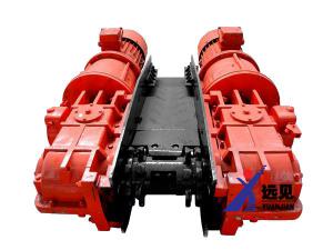
The scraper conveyor is mainly composed of a transmission device, a supporting beam, a transition slot, a middle slot, a scraper chain, and a tail (see Figure 1).
The design length of the scraper conveyor is 80 meters. In use, it can be lengthened or shortened according to the actual situation of the working surface.
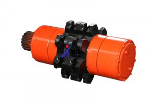
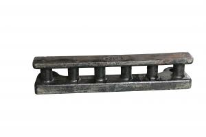
The transmission device (Figure 2) is the transmission mechanism of the product, which is mainly composed of motors, reducers, head sprockets, head frames, couplings and other components. The reducer is mounted on the side plate of the head frame with four M24 bolts, the motor is connected to the reducer through the connection cover, the drive shaft of the reducer is connected to the motor through the wooden pin coupling, and the output shaft of the reducer is inserted The support hole on the side plate of the head frame is connected with the sprocket of the head by a key. When transmitting power, the motor transmits the torque to the reducer through the wooden pin coupling, and then transmits the torque to the machine head sprocket after deceleration, driving the scraper chain to move in the middle groove to achieve the purpose of transporting coal. In order to facilitate the overall pushing conveyor, the pushing beam and the supporting beam are installed at the lower part of the head frame.
The reducer (figure 3) is a three-stage gear transmission mechanism, which is composed of a pair of arc bevel gears, a pair of helical cylindrical gears and a pair of spur cylindrical gears.
Table 1
series | Gear Modulus | Gear helix angle | Large gear teeth | Pinion teeth | Speed ratio |
***level | 5 | β = 33 ° 44′56 ″ | 36 | 14 | 2.57 |
second level | Mn = 5 | β = 10 ° | 44 | 13 | 3.38 |
Third level | 6 | 43 | 15 | 2.87 | |
Total speed ratio | 24.95 | ||||
The exposed shaft extension of the second shaft of the reducer is used for installing the chain tightener ratchet.
The fourth shaft of the reducer is a hollow shaft structure. The torque transmitted by the motor is first transmitted to the hollow shaft, and then transmitted to the shaft fixed with the machine head sprocket through the safety pin. During the operation of the conveyor, such as overload or scraper chain scraping and other unacceptable abnormal conditions, the safety pin will be cut off, so that the torque of the motor cannot be transmitted to the sprocket of the machine head, which plays a role in protecting the motor and the chain.
The box mechanism of the reducer is symmetrical from top to bottom, and can be used by turning 180 degrees to meet the needs of coal mine installation. When turning it over, install a vent plug on the upper oil cap and an oil plug on the lower oil cap.
note:
Mounted on the other side of the machine head sprocket to support the blind shaft (Figure 4), it is composed of sprocket, bearing housing, rolling bearing, bearing cover, etc. The bearing seat is fixed on the side of the head frame by four M24 bolts, and the exposed shaft extension is connected to the head sprocket with a key.
There is also a chain puller installed on the machine head frame, its function is to prevent the scraper chain from being wrapped around the machine head sprocket and causing damage to other parts.
The chain tensioner is used for tensioning the scraper chain when the conveyor is installed, disassembled or the length of the laying is changed. Its structure is as shown in (figure 5). The ratchet for installing the chain tensioner is installed on the exposed shaft of the second shaft of the reducer, and the base is installed on The third shaft has a boss on the bearing cover. When the conveyor is running normally, the ratchet rotates counterclockwise. At this time, the roller on the fork is pressed against the lower part of the pawl groove (as shown by the dotted line in the figure), so that the pawl tip of the pawl is separated from the tooth of the ratchet. (Note: The tight chain handle should be removed during normal operation)
For the tightening chain operation, first put the handle on the boss of the shift fork and pull it to the position shown in the figure. At this time, the shift fork moves the pawl so that the tip of the pawl contacts the tooth of the ratchet wheel, and the jog motor rotates in the reverse direction. Turn the ratchet wheel clockwise, the chain is tensioned (the upper end of the chain of the scraper chain should be connected to the tight chain hook first, and the other end of the tight chain hook is inserted into the hole in the side plate of the head frame. (On the sprocket of the machine head, the end of the chain is pulled by hand). After the chain is tensioned, the motor stops running in reverse.
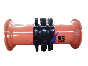
The head frame and the middle groove of the transmission device are connected by a transition groove, and the transition groove is connected to the head frame by a bolt and the middle groove is connected by a bolt. There are three M16 screw holes on each side of the transition groove for the installation of the transition groove The structure of the baffle and the transition groove is as follows (Figure 6).
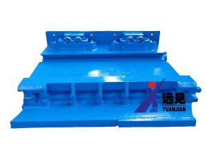
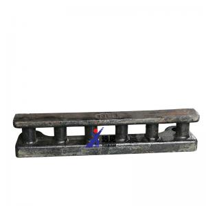
The structure of the middle slot is as shown in (Figure 7). It is integral. During installation, the side of the welding port plate is downward, and the side where the slot is open is upward. The grooves of a section of grooves can be deflected up and down, left and right by 3 to 4 degrees during use.
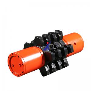
The scraper chain is the working part of the conveyor for coal transportation. It is composed of a ring link, a scraper, and a live joint. (Figure 8) The ring link is 9.85 meters long. The scraper is fixed to the flat of the ring link with U-shaped bolts. On the ring, the scraper spacing is generally 700 mm, but it can also be increased or decreased according to the actual situation. The various chains are connected together with unions. When connecting, half of the joint (link head) is fixed with a U-shaped bolt to the link head and the link ring at both ends of the ring (note that at this time the two link head fisheye pits installed on both ends of the same ring chain should be Same side). Then hang the joints of the two end parts of the two endless chains that need to be connected together on the bosses respectively on another soil platform with pin holes, and install cotter pins in the pin holes to fix them. In order to meet the needs of different laying lengths of the conveyor, ten kinds of circular chains with different lengths are randomly provided for installation and selection.
The tail is the guide device of the scraper chain, which is composed of the tail frame and the tail shaft and other components. Its structure is as shown in (Figure 9). The small end of the tail frame is directly connected with the middle slot with bolts, and the tail shaft is used with a plug It is fixed to the end of the tailstock with a fork. The outriggers on both sides of the tailstock can support the pillar of the tail. The tail shaft component (Figure 10) consists of the shaft, tail sprocket, bearing, oil seal, etc. Composition, when running, the tail sprocket rotates on the shaft and the shaft and the tail frame are fixed together.
3. Installation and test
1. Before the product is installed on the working surface, the components should be installed in the underground installation location and numbered separately, and then shipped to the installation site in sequence. The accessories and tools used during installation and various connection parts should also be classified according to specifications and varieties Take to the underground installation site.
2. Installation order of transmission part
⑴. At the installation site, connect the head frame with the push beam and the support beam
⑵, Place the reducer, connecting cover and motor in order on the side of the goaf of the head frame, and install the connecting plate of the wooden pin coupling on the shaft diameter of the motor and reducer (also can be installed on the well Good, and then shipped to the installation site)
(3) Install the reducer on the head frame (on the side of the mined-out area), and the sealing jacket flange of the fourth shaft of the reducer should coincide with the support hole of the head frame. The keyway on the side should match the guide flat key installed on the side plate of the head frame.
⑷. Install the coupling cover on the end flange of the reducer, and then install the motor on the coupling cover.
When conditions permit, motors, coupling hoods, speed reducers, etc. can also be connected together on the shaft in advance, and then transported to the installation site as a whole and installed on the head frame.
⑸, install the machine head sprocket on the shaft extension of the fourth shaft of the reducer
⑹ 、 Install blind shaft on the other end of the sprocket
⑺ 、 Install the wooden pin on the wooden pin coupling and lock it with iron wire
⑻ 、 Inject 11 # cylinder oil into the reducer, the injection volume should submerge 1/3 of the diameter of the large bevel gear
3. Install the transition groove and transition groove baffle, and install the scraper chain in the lower tank body. When placing the scraper chain, pay attention that the ring cannot be twisted.
4. Install the lower groove scraper chain and the middle groove in sequence. When the scraper chain is connected, the cotter pin on the joint should be opened to prevent the pin from falling off.
5. After installing the tail, install the scraper chain in the upper groove within the laying length of the whole machine, and fix the pillar on the top of the tail and the transmission parts.
6. Connect the power supply and test the direction of the motor. Before the test, the scraper chain should be disconnected from the sprocket of the machine head.
7. Tension the scraper chain, first put the scraper chain that protrudes from under the nose frame on the nose sprocket, and the other end is fixed on both sides of the nose frame with a tight chain hook. "Closed position" makes the pawl contact with the ratchet wheel, and the scraper chain of the motor is tensioned in the reverse jog. After the scraper chain is tensioned, select the appropriate length of the adjustment chain and connect it. Then, reverse the jog motor to pull the tightening chain handle to disengage the pawl from the ratchet wheel, and then move the motor forward to remove the tight chain hook.
8. Start the conveyor and run it at no load for 1 to 3 weeks, carefully check whether the scraper chain and other components are installed correctly, and whether the scraper is stuck.
9. After checking and adjusting the normality of each part, it should be driven to run continuously at no load for 15 minutes to half an hour to further check the conveyor installation. If problems are found, adjust or eliminate them.
10. After the no-load operation test is normal, a full-load coal pulling test should be conducted.
11. After everything is normal, the conveyor can be delivered for use.
Four, use and maintenance
1. Operation: After the conveyor is normally delivered for use after testing, the length of the segmented blasting should be determined according to the actual situation of the working surface, in order to enable the machine to start normally.
When the machine is started, it should be jogged to check. Whether there are any abnormal conditions in the transmission parts of the transmission part, and whether there is scraping of the scraper chain, etc., after normal, the conveyor can be started to start coal transportation.
During the operation of the machine, the operator should pay attention to observe the operation of the machine, and check the temperature rise of the bearing parts of the motor and the reducer according to the regulations. If any abnormal conditions are found, they should immediately stop the machine and check and eliminate the failure in detail.
2. Replacing the safety pin: when the machine is running, if an abnormal situation such as a scraper chain or card is caught, the safety pin will be cut off when the motor is overloaded. At this time, the fault should be checked first, and the insurance will be cut off after the fault is removed. Pin out and replace with new insurance pin.
3. Moving machine: the conveyor adopts manual manual sliding, no need to disassemble and reinstall, the chute is lighter, generally adopts the crowbar to move, the transmission part is heavier, you can use the winch or other traction device in the working surface, the movement is completed After that, fixed pillars should be laid on both the head and the tail.
4. Adjust the scraper chain: If the scraper chain is found to be too loose or too tight during the operation of the machine and the laying length needs to be changed due to changes in the working surface, the scraper chain must be disassembled and the chain tightened again. The same as the previous installation.
5. Schedule maintenance
(1) After the conveyor is moved, a comprehensive inspection should be conducted first to check whether the transmission parts are safe and reliable, whether the connection interfaces are correct, and whether the scraper chain and the chute are scratched.
⑵ After each part is checked, no-load operation test should be conducted to check its operation.
(3) Check the temperature rise of each bearing part of the conveyor according to the regulations and fill or change the oil regularly.
⑷. Check the sealing condition of each sealing part frequently. If the leakage of oil is serious, replace it within the maintenance class. Generally, replace it as planned.
⑸. The scraper chain of the conveyor should be thoroughly inspected once a day by the maintenance team. If the scraper or joint is found to be loose, the U-shaped screw should be re-tightened to prevent the scraper, joint and other parts from falling off or being lost during operation.
1. Bearing List
Code | Name specification | Quantity | Installation location |
GB288 / T-1994 | Rolling bearing 3510 | 2 | Tail shaft |
GB288 / T-1994 | Rolling bearings 3612 | 1 | Blind shaft of transmission |
GB288 / T-1994 | Rolling bearings 3003124, 3520 | Each 1 | Reducer fourth axis |
GB297-64 | Rolling bearing 7610 | 4 | Reducer ***, two axes |
GB297-64 | Rolling bearings 7611 | 2 | Reducer third axis |
GB309-64 | Needle roller φ6 × 50 | 82 | Reducer fourth axis |
2. List of oil seals
Serial number | Code | name | Quantity | Installation location |
1 | HG4-692-67 | Oil seal 45 × 62 × 12 | 1 | Reducer *** shaft |
2 | Oil seal 50 × 72 × 12 | 3 | Reducer second shaft, tail shaft | |
3 | Oil seal 75 × 100 × 12 | 1 | Blind shaft of transmission | |
4 | Oil seal 85 × 110 × 12 | 1 | Reducer fourth axis | |
5 | HG4-692-67 | Oil seal 130 × 160 × 12 | 1 | Reducer fourth axis |
6 | HG4-333-66 | "O" type sealing ring 85 × 3.1 | 1 | Reducer fourth axis |
7 | HG4-333-66 | "O" type sealing ring 130 × 3.1 | 1 | Reducer *** shaft |
8 | HG4-333-66 | "O" type sealing ring 110 × 3.1 | 1 | Reducer *** shaft |
3. Lubrication of the machine
Serial number | Oil injection part | Oil injection points | Lubricating materials | Lubrication method | Filling cycle |
1 | Motor bearing | 2 | Calcium sodium base grease | Manual oil injection | 3 months cleaning and oil change |
2 | Reducer gear | 1 | Ⅱ cylinder oil | Dumping oil can | Oil injection once a month, clean and change oil in 3 months |
3 | Reducer ***, four-axis oil injection hole | 2 | No. 2 sodium base grease | Manual oil injection | Once a month |
4 | Reducer second, third and fourth shaft bearings | 6 | Gear splash oiling | Oil injection | |
5 | Blind shaft bearing | 1 | Manual oil injection | Once a month | |
6 | Tail shaft bearing | 2 | Manual oil injection | Once a month | |
7 | Chain tension ratchet and pawl | 2 | Ⅱ cylinder oil | Oiler | Once a month |
Tips: willing to spend a lot of money for products, not to buy fakes cheaply
Please look for Luoyang Yuanjian Mining Equipment Co., Ltd. ,assured products in the market.
Luoyang Yuanjian Mining Equipment Co., Ltd.